Semi-Procedural Photoscan Materials

Our Workflow for Crafting Semi-Procedural Material Textures from Photoscans In the ever-evolving landscape of 3D modelling and texture creation, we've developed a method that merges the authenticity of real-world materials with the power of digital tools. Today, we're excited to share our detailed workflow for generating semi-procedural material textures directly from photoscans. This technique enriches our projects' realism and adds depth that can be challenging to achieve through digital means alone.
The Tools We Use To facilitate our process, we rely on several industry-standard software applications:
- Darktable: For photo editing and colour correction.
- Agisoft Metashape: For converting photos into detailed 3D meshes.
- Blender: To transform the high-poly scan mesh into a low-poly representation.
- Substance Designer: For baking textures and constructing rich material layers.
DEFINING THE CAPTURE AREA
Our workflow begins with meticulous planning. We define a 2m x 2m area that we want to capture—this area serves as our canvas. To ensure precision, we use 2-meter-long stick rulers as reference points. This helps us outline the desired space accurately while providing a scale for our mesh, ensuring everything is rendered to true dimensions.
CAMERA SETTINGS
Before capturing textures, we prepare for colour accuracy by photographing a colour checker chart. This chart is crucial for colour correction during our editing phase in Darktable.
Next, we set up our camera with a 50 mm focal length on a full-frame body. We lock the white balance for consistency and adjust the shutter speed between 1/60 and 1/250 seconds to find the perfect balance of stability and speed, capturing clear images even in varying lighting. We also set the aperture around f/5 to f/8 to achieve an optimal depth of field, ensuring our subjects remain in sharp focus. Depending on the weather, we may use auto ISO or lock it to adapt to the ambient light.
PHOTOGRAPHING
With our settings adjusted and the colour checker in place, we begin capturing a series of images within the designated area. It is crucial to ensure that the images overlap sufficiently so that Agisoft Metashape can stitch them together seamlessly. We always start with the sunlight positioned in front to avoid casting shadows.
Next, we move side to side, taking small steps until we photograph the entire area. By the end of this process, we aim to capture around 200 photos in total.
Once we have finished, we take a black photo. This is useful for easily identifying the end of the capture session. Taking this black photo makes it simpler to separate images, particularly when photographing materials that have a similar appearance, such as sand.
PROCESSING THE PHOTOS
Once we've gathered all our images, we turn to Darktable for colour correction, adjusting exposure, applying a slight sharpening effect, and minimising shadows as much as possible. We can calibrate the colours using a photographed colour checker chart to ensure our images accurately reflect reality. This step is crucial for creating realistic textures.
Next, we convert the raw photos into a format compatible with Metashape. While JPEG or EXR formats are commonly used, it's better to use EXR or PNG because they don't compress the images, but can quickly consume storage space. In many cases, the differences may not be noticeable in the final output.
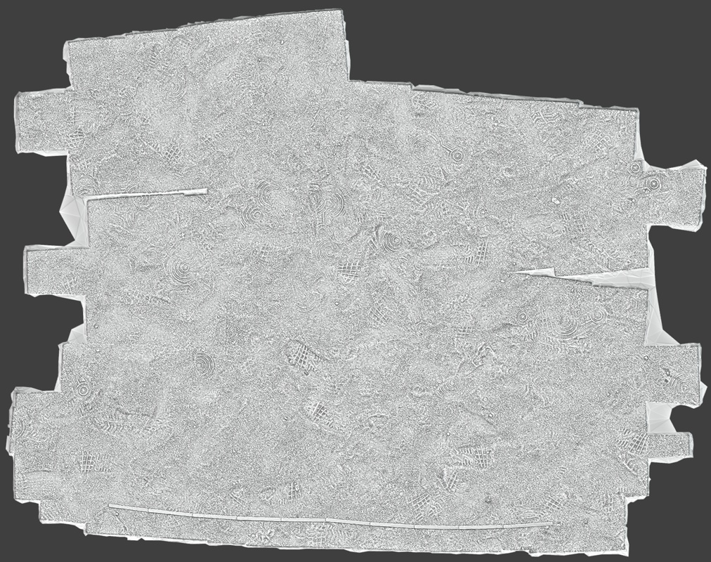
After editing, we import our images into Agisoft Metashape. This software processes the photos and constructs a detailed 3D mesh that captures the intricate details of the area we are focusing on. We import the images and initiate the processing method to create the photogrammetry model. Depending on the number of photos, their resolution, and the desired quality of the mesh, this can take some time.
Once processing is complete, we will have a mesh with over 1 million polygons. Before extracting colour information from the photos, we must create a bake plane from the scan onto which we will project the scan data. This will be used to extract the height data.
BAKE PLANE
First, we reduce the scan mesh to approximately 10,000 to 50,000 polygons. We then export this mesh as a high-poly model and import it into Blender.
In Blender, we have a custom geometry node setup that simplifies creating and placing a subdivided plane. This setup allows us to correct the plane's position, rotation, size, and deformation to align with the high-poly mesh.
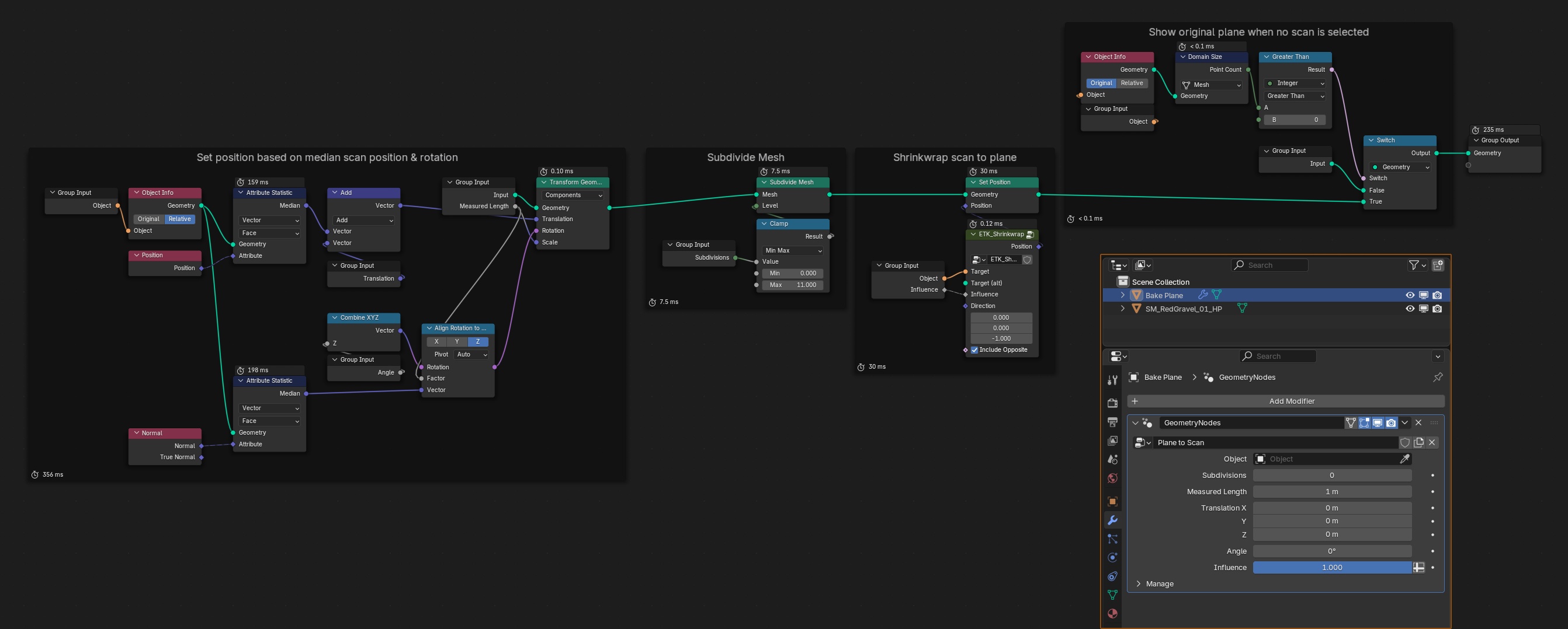
In the input parameters, select the high-poly object, and the plane will be positioned approximately correctly. Use the measurement tool to measure the ruler in the scan and adjust it to the correct size. The additional options allow us to tweak the position and angle of the plane for better alignment with the surface if necessary.
We want to cover as much area as possible within a 2x2 region while avoiding areas with lower density or holes. Some holes near the borders are acceptable because we will create a circular mask in Substance Designer to ensure the material is tileable.
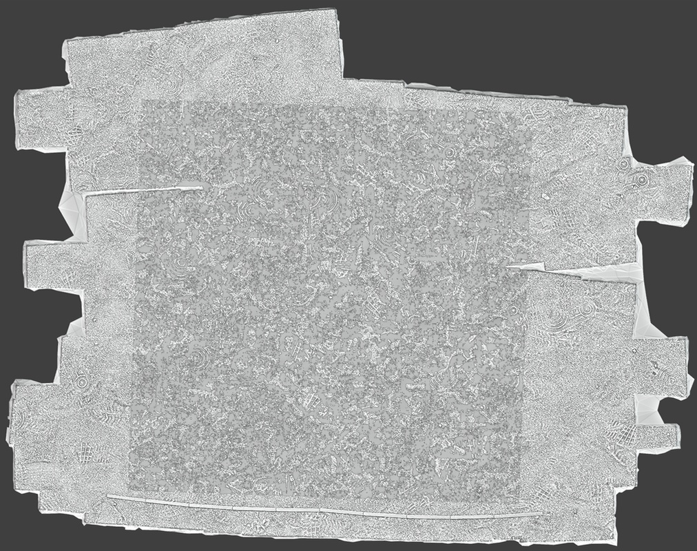
Projecting the plane onto the high-poly mesh minimises height differences and captures only the high-frequency variations in height. This approach makes it harder to detect tiling seams. Managing those in the terrain mesh or using other methods to hide texture seams effectively is typically better for significant height deformations.
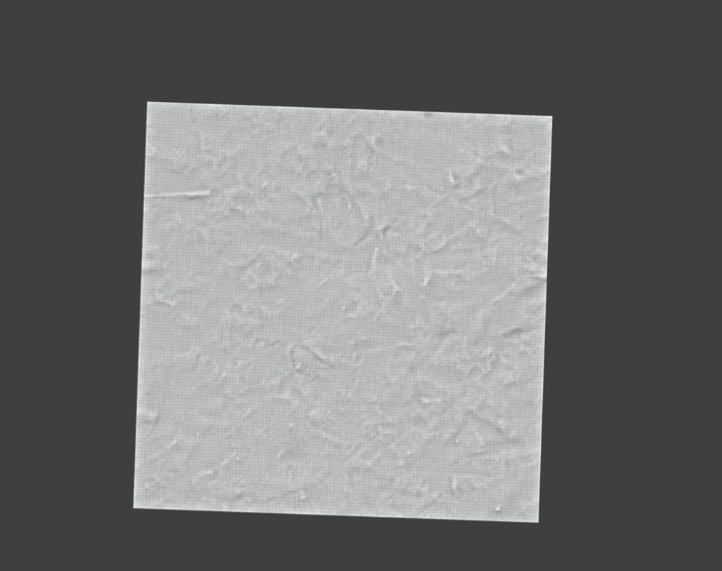
Once we are satisfied with the plane's placement and deformation, we can export it as a low-poly mesh and import it back into Metashape to bake the diffuse map.
PROJECTING DIFFUSE MAP
Import the new mesh. If the plane is in the same position as the original, we can start baking the diffuse map. We only want to bake the diffuse texture in Metashape; all other maps, such as normal, ambient occlusion, thickness, and height, will be baked in Substance Designer. The texture-baking process in Substance Designer is much faster compared to Metashape, and the results are nearly identical. When the texture is done, we export it and the original scan mesh.
TEXTURE BAKING
In this step, we will bake the necessary maps to create a realistic material. We want to bake the normal, ambient occlusion (AO), thickness, and height maps onto the low-poly plane. First, we will link the low-poly mesh, the scanned mesh, and the diffuse map.
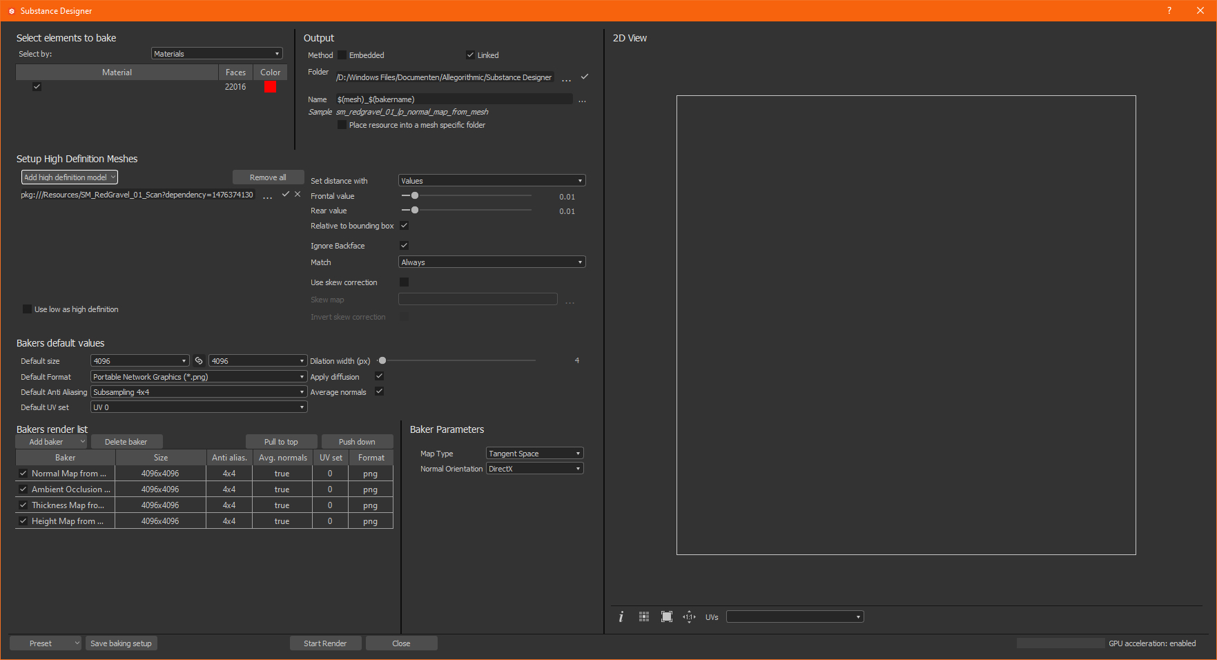
We will generate a thickness map to help create a base roughness map. All textures will be baked at a resolution of 4K with 4x anti-aliasing (AA). You can certainly go higher if your computer is powerful enough, but we typically export the final textures at 4K. For our needs, 4K baked textures are sufficient.
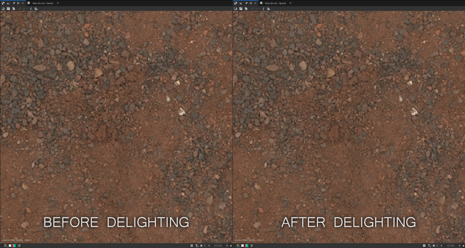
DELIGHTING
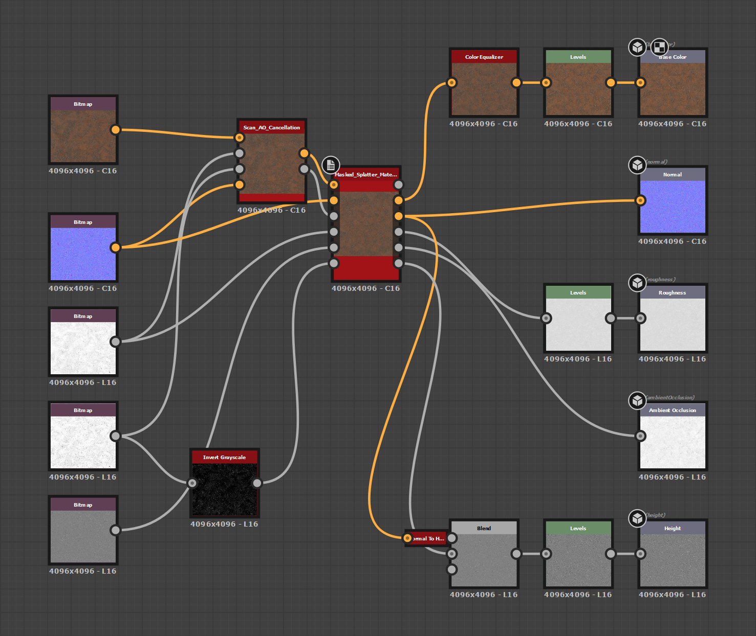
We can begin delighting the diffuse texture with everything set up and ready. The next step involves configuring the nodes for Ambient Occlusion (AO) cancellation of the diffuse map and creating the roughness map.
We have two methods for delighting the diffuse texture. The first method uses the native AO Cancellation node that comes with Designer, while the second involves a custom setup using Color Equalizer with AO as a mask. Both approaches are effective, but they exhibit slight differences. We often test both methods to determine which removes the most shadows while minimising artefacts.
Additionally, we apply a slight sharpening effect to enhance the details and make them stand out more.
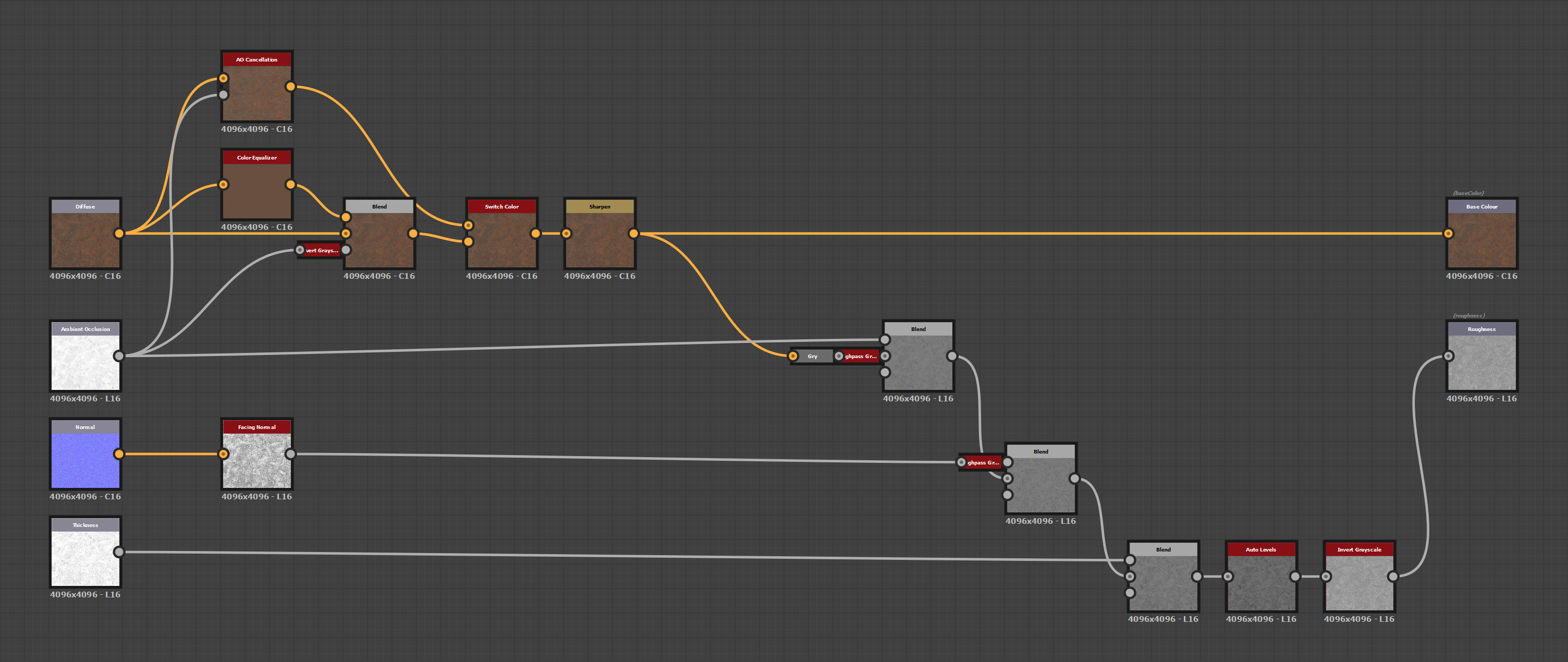
ROUGHNESS MAP
To create the roughness map, we convert the base colour to grayscale and apply a high-pass filter. This gives us our base roughness. Next, we multiply this base roughness with the ambient occlusion (AO) map. This step darkens areas that are occluded, which are typically rougher due to the presence of dirt and grime. When applying roughness, this results in a shinier appearance, so we later invert the output.
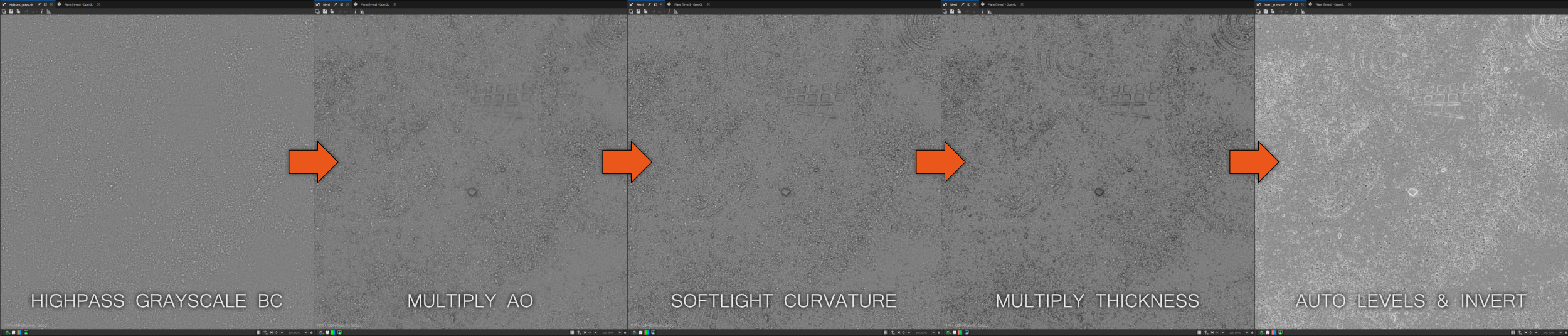
The next step is to add detail from the normal map, which enhances sharp edges. We analyse the normal map to assess the facing normal (i.e., how much is facing upwards) and then pass this through a high-pass filter. This process is similar to generating a curvature map. We blend this result with our base roughness using a soft light blending mode.
The final step involves multiplying the result by the thickness map. Thinner areas (darker values) tend to be rougher, while thicker areas are smoother. Afterwards, we auto-level the map to ensure the values cover the entire 0-1 range and invert it.
After completing these steps, we derive our base colour and roughness map. Additionally, we can fine-tune the values at each blending stage to better match the specific material we are trying to recreate.
MAKING TEXTURES TILEABLE
We can create tileable versions of our current textures and export them. However, doing so would result in only a single material, which is not ideal for efficiency. To gain more value from our efforts, we aim to maximise the number of variations from this material.
The following graph setup will make our material semi-procedural and tileable. This process can be technical and involves several pixel processor nodes and FX map node graphs.
Here's a brief overview of the concept:
- Select an Area: We begin by choosing a specific area within the texture space we want to repeat.
- Rotate and Offset: Next, we rotate this area and apply a random offset.
- Blend Elements: We blend these elements based on a mask, such as a height map.
We repeat this process for all the different maps, resulting in a semi-procedural surface scan material. While the process sounds straightforward, executing it presents several challenges.
MASK
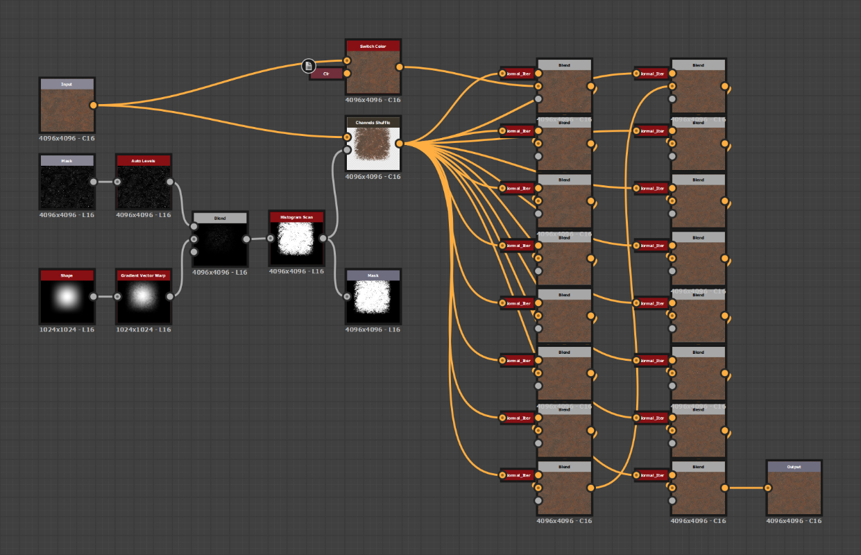
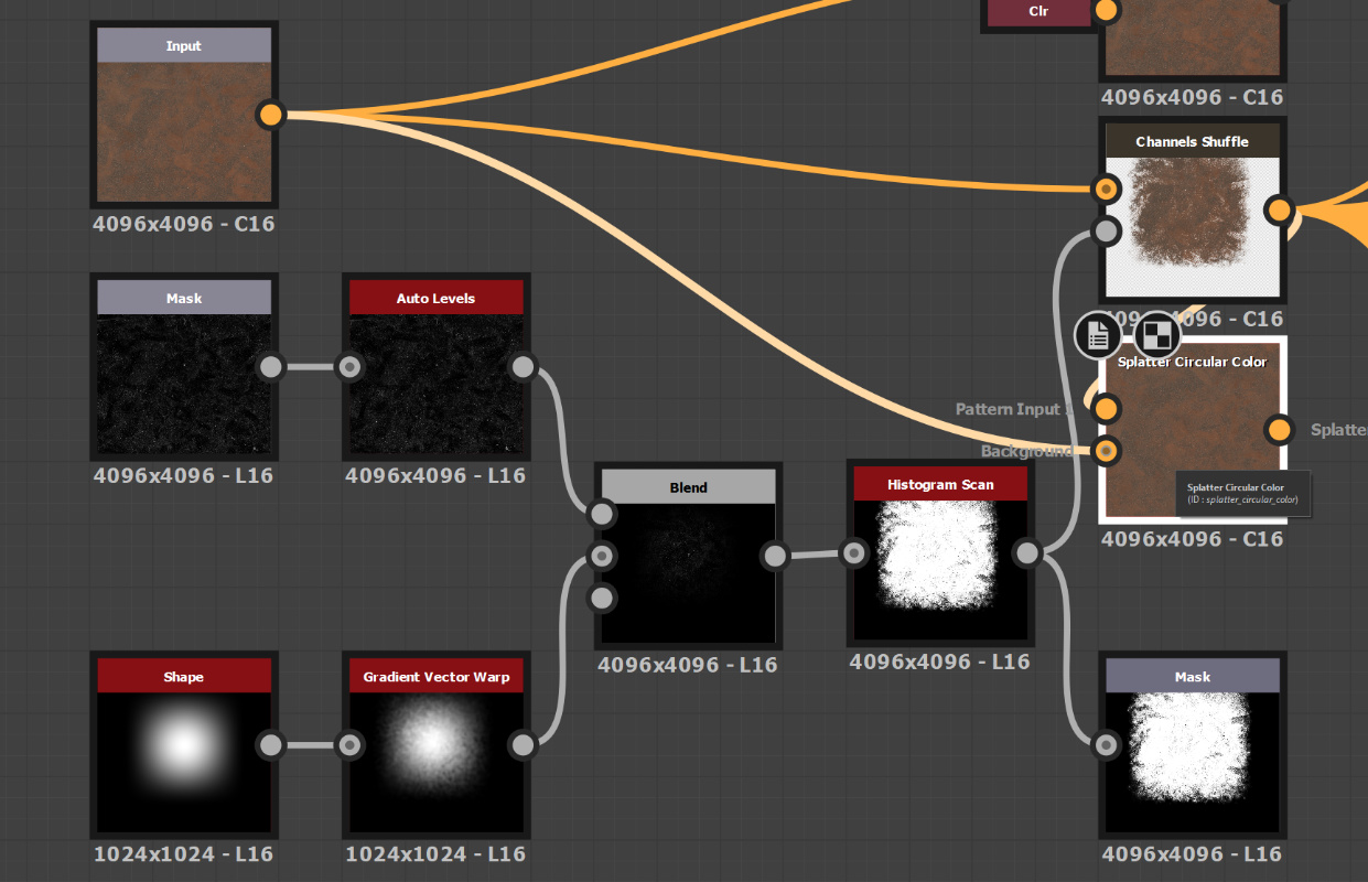
Let's start with the easy part: creating the main mask for the area we want to tile. We use the shape node as the base for our mask and expose the pattern, pattern-specific, and scale parameters, allowing us to fine-tune the shape and experiment.
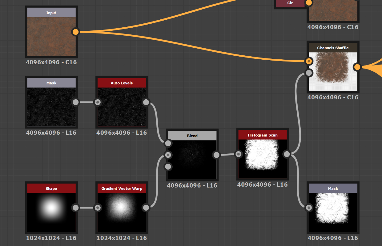
We warp the shape using a gradient vector warp to add complexity to our mask and hide the tiling effect. This custom node smoothly warps any input. After that, we multiply our shape with a mask input and feed it into a histogram scan. This creates our main shape, where we can control the transition area's contrast and the masked input's details.
The last step is to combine it with our colour input and set the mask as the alpha channel. This creates a stamp texture or decal.
SPLATTER TEST
Let's test our decal and see how it works.
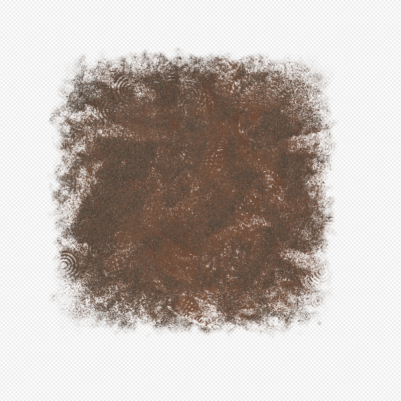
Using a Splatter Color node, we can duplicate the decal multiple times and fill the texture space. Spotting the seams of the textures is difficult. However, we have some areas where no stamp is applied in this case.
To address this issue, let's use the original colour input as a background and place all the stamps on top of it. By doing this, we eliminate any empty spots, and the stamps effectively conceal the seams at the edges of the texture.
This approach works great for the base colour, but we need to do something extra for the normal map. If we plug the normal map in instead of the base colour, the position and rotation remain the same as before. However, the direction of the normal map changes because of the rotation applied. We need to reorient the normal map in the opposite direction of the rotation it receives from the Splatter node. Fortunately, we can accomplish this using the Normal Vector Rotate node.
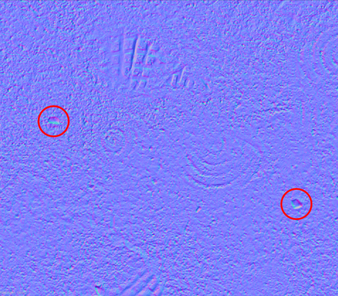
However, there is a problem. If we want to reorient the normal map, we cannot use the Splatter node, as it does not have the option to rotate each iteration. We can only perform the rotation beforehand, which does not resolve our issue.
CUSTOM SPLATTER
So instead, we have to make our own splatter node. We do this with a pixel processor, value processor, normal vector rotation and transformation 2D nodes.
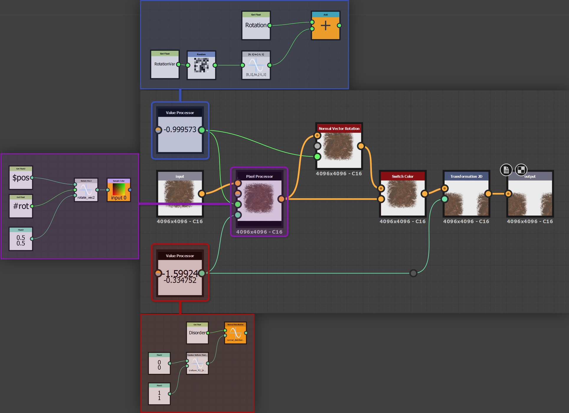
The logic for the value and pixel processor nodes is relatively straightforward. We calculate a random rotation between -1 and 1. This is then used to rotate the decal/stamp texture. If it is a normal map, we use this rotation to correct the normals. Then we calculate an offset value also between -1 and 1, and this is plugged into the transformation 2D node to translate the rotated texture. We expose a couple of parameters such as rotation, rotation variance, disorder and isNormal, and that's our custom splatter node finished.
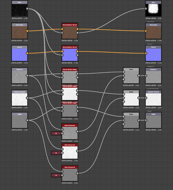
Next, we need to make our blend tree where we can blend several stamps. To do this, we offset the random seed of each custom splatter node and combine the previous iteration with the next. Do this for how many iterations you want; we use a maximum of 16 iterations. Expose and link all the parameters of the custom splatter node, linking it up with the main colour input and stamp texture. Everything is now ready to be used.
Next, we do the same for the other maps, AO, height, and roughness, and we have our semi-procedural material. However, we also add a small falloff area around the masked area, which makes the transition more seamless for significant differences in height.
The performance of this graph is quite heavy, because it has to copy the input texture, at 4k or higher, multiple times and do this for all the other maps as well. So we first lower the absolute size of the node setup when altering its parameters. This will make it much easier and faster to edit. Changing the random seed of the node will randomise the placement and rotation of the stamps and thus give us an entirely new tileable material. This is extremely useful if you want to break up the tiling on, for example, a terrain.
And because this setup is generalised, we can use it for various types of non-uniform materials. For uniform materials such as a brick wall, this setup doesn't work. But we are working on a generalised setup for that as well; it just has a lot more requirements.
CONCLUSION
So this concludes our workflow for creating semi-procedural material textures from photoscans. We like this setup and the flexibility it offers to create variations of the same material scan.
For now, our workflow uses Substance Designer for the final processing step; however, we would like to do this step inside Blender. Because we don't like the reliance on paid software (we even used an old version of Designer before it became a subscription), and minimising the switching of software packages makes it much simpler to process the materials.
So if you are looking to create a lot of materials, we recommend trying this workflow out for yourself and seeing if it benefits you.